We use cookies to make your experience better. To comply with the new e-Privacy directive, we need to ask for your consent to set the cookies. Learn more.
CSE16504 RazorMax Express
CSE16504 RazorMax Express
4 Ch, 500 MS/s, 16-bit, 350 MHz BW, 4 GS buffer
FEATURES
- 16-bit Vertical A/D Resolution
- 4 Ch, 500 MS/s sampling per Ch
- Software Selectable Sampling Rates, 1 kS/s - 500 MS/s
- 350 MHz Bandwidth
- 4 GS (8 GB) Onboard Sample Memory
- Timestaping data capability
- Real-Time FPGA/DSP Functions
- 6 GB/s Sustainable Data Streaming
- DC Coupling 50Ω Inputs , AC coupling (optional)
- Input Voltage Ranges ±1 V or ±240 mV ( choose when ordering)
- External or Reference Clock In & Clock Out
- PCI Express Gen 3.0 x8 Single-Slot Card
- Multiboard Synchronization
- Windows 10/8/7 and Linux
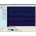
- GaGeScope PC Oscilloscope Software
- SDK for C/C#, LabVIEW and MATLAB
CSE16504 RazorMax Express
4 Ch, 500 MS/s, 16-bit, 350 MHz BW, 4 GS buffer
Analog Input Front End
The RazorMax Express is available in quad channel and dual channel models supporting a maximum A/D sampling rate up to 1 GS/s or 500 MS/s. ADC data can be captured in quad channel, dual channel, or single channel modes. The analog input bandwidth is 700 MHz for the 1 GS/s sampling rate models, and is 350 MHz for the 500 MS/s sampling rate models. The input channels are fixed for DCcoupling with fixed 50 Ω input impedance. The wider 700 MHz bandwidth is especially useful for RF based applications by enabling direct RF sampling of wider band signals. A configuration for fixed AC-coupling with fixed 50 Ω input impedance is available as an option. The coupling front end is factory hardware configured and is not software switchable. Note that it is also possible to externally implement ACcoupling with the use of an external high-pass filter. ACcoupling is useful for applications in which a small AC signal is sitting upon a large DC bias. In these cases, the DC bias can be removed with AC-coupling to reduce the input range for better signal fidelity
RazorMax Express models have factory hardware configured single fixed input voltage range of either ±1 V or ±240 mV. These fixed input voltage ranges can be effectively increased through the use of attached inline SMA attenuators if required; see Attenuator Options section.
DC Clock Circuit
The RazorMax Express utilizes an onboard fixed master crystal oscillator as the primary internal clock source for the ADCs combined with clock control to effectively produce 31 software selectable A/D sampling rates ranging from 1 kS/s to 1 GS/s with a rate accuracy of ±1 Part Per Million (PPM). The ADC clock can also be supplied by an external clock input source, allowing for variable clock sample frequencies from 250 MHz to 1. External clock input signals are routed almost directly to the ADC chips so that each clock edge causes the ADC chips to produce exactly one sample. No re-clocking or Phase Lock Loop circuitry is used, since these methods may lead to extra or missing ADC clocks.
Use of an external clocking signal that is synchronous with the signal to be acquired achieves the best possible trigger stability with intrinsic jitter typically ¼ of a data point or better. Compared to using an internal clock source that is asynchronous (unrelated) to the signal trigger that can result in a 1 point trigger jitter between acquisitions.
When internally clocking, the ADC clocking signal is produced by a Voltage Controlled Crystal Oscillator (VCXO) within an on-board Phase Lock Loop (PLL) circuit. The PLL is disciplined by an on-board 10 MHz reference signal that has a frequency accuracy of order ±1 PPM. This circuitry ensures that the frequency of the VCXO is reset every 100 nanoseconds so that the ADC sampling clock inherits the accuracy and stability of the 10 MHz reference input.
The ±1 PPM internal sampling rate accuracy is sufficient for most digitizer applications. However some applications (notably communications), require ultra-high ADC clocking accuracy and stability. External atomic or IRIG sources can provide 10 MHz reference frequency accuracies and stabilities that are measured in Parts-Per-Billion. For these requirements, an external 10 MHz reference clocking signal source can be applied to the external clock input. Activating reference clocking from the controlling software will switch the PLL/VXCO input from the digitizer’s 10 MHz reference signal to the supplied external 10 MHz reference signal. The ADC sampling will then inherit the accuracy and stability of the supplied external 10 MHz reference signal. A clock output connector can be used to provide a clock out signal to serve as an external clocking source for other external devices. The clock out signal frequencies range from 250 MHz to 1 GHz, or can be configured to output the onboard 10 MHz reference signal.
Acquisition Memory
The RazorMax Express includes 4 GS (8 GB) of onboard acquisition sample memory. The onboard acquisition memory size is shared and equally divided among all active input channels (4, 2, or 1) when acquiring data to onboard memory. With the optional eXpert PCIe Data Streaming FPGA Firmware package, the dual-port architecture of the onboard memory is utilized as a large FIFO buffer for streaming acquired data to host PC memory via the digitizer’s PCIe Gen3 x8 interface at sustained rates up to 6 GB/s. This streaming mode can be effectively utilized to conduct real-time sustained host-based signal processing and/or signal recording operations of the acquired data.
| Specifications | RazorPlus Express Series Specification
|
||||||||||||||||||||||||||||||||||||||||||||||||||||||||||||||||||||||||||||||||||||||||||||||||||||||||||||||||||||||||||||||||||||||||||||||||||||||||||||||||||||||||||||||||||||||||||||||||||||||||||||||||||||||||||||||||||||||||||||||||||||||||||||||||||||||||||||||||||||||||||||||||||||||||||||||||||||||||||||||||||||||||||||||||||||||||||||||||||||||||||||||||||||||||
|---|---|---|---|---|---|---|---|---|---|---|---|---|---|---|---|---|---|---|---|---|---|---|---|---|---|---|---|---|---|---|---|---|---|---|---|---|---|---|---|---|---|---|---|---|---|---|---|---|---|---|---|---|---|---|---|---|---|---|---|---|---|---|---|---|---|---|---|---|---|---|---|---|---|---|---|---|---|---|---|---|---|---|---|---|---|---|---|---|---|---|---|---|---|---|---|---|---|---|---|---|---|---|---|---|---|---|---|---|---|---|---|---|---|---|---|---|---|---|---|---|---|---|---|---|---|---|---|---|---|---|---|---|---|---|---|---|---|---|---|---|---|---|---|---|---|---|---|---|---|---|---|---|---|---|---|---|---|---|---|---|---|---|---|---|---|---|---|---|---|---|---|---|---|---|---|---|---|---|---|---|---|---|---|---|---|---|---|---|---|---|---|---|---|---|---|---|---|---|---|---|---|---|---|---|---|---|---|---|---|---|---|---|---|---|---|---|---|---|---|---|---|---|---|---|---|---|---|---|---|---|---|---|---|---|---|---|---|---|---|---|---|---|---|---|---|---|---|---|---|---|---|---|---|---|---|---|---|---|---|---|---|---|---|---|---|---|---|---|---|---|---|---|---|---|---|---|---|---|---|---|---|---|---|---|---|---|---|---|---|---|---|---|---|---|---|---|---|---|---|---|---|---|---|---|---|---|---|---|---|---|---|---|---|---|---|---|---|---|---|---|---|---|---|---|---|---|---|---|---|---|---|---|---|---|---|---|---|---|---|---|---|---|---|---|---|---|---|---|---|---|---|---|---|---|---|---|---|---|---|---|---|---|---|---|---|---|---|---|---|---|---|---|---|---|---|---|---|


