We use cookies to make your experience better. To comply with the new e-Privacy directive, we need to ask for your consent to set the cookies. Learn more.
CSE25216 RazorPlus Express
CSE25216 RazorPlus Express CompuScope, 2Ch, 250 MS/s, 16 bit, PCIe Gen3
FEATURES
- 2Ch, 16 bit A/D, Simultaneous input
- 250 MS/s Maximum Sampling Rate per Channel
- 150 MHz Analog Input Bandwidth
- Software Selectable Sampling Rates, 1 kS/s to 250 MS/s
- 4 GS (8 GB) memory buffer, Expandable up to 8 GS (16 GB)
- Sustained PCIe Data Streaming at 1.6 GB/s
- Full-Featured Front-End, AC/DC Coupling, 50 Ω /1M Ω Inputs
- External or Reference Clock In/Clock Out
- Supports Multi-Card Synchronization
- Supports Optical Coherence Tomography (OCT)
- Full-Height Full-Length PCI Express Gen 3.0 x8 Card
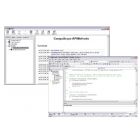
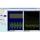
- GaGeScope PC Oscilloscope Software
- SDK C/C#, LabVIEW and MATLAB
- Windows, Linux OS Supported
- RADAR Design and Test
- Signals Intelligence (SIGINT)
- Ultrasonic Non-Destructive Testing
- LIDAR Systems
- Communications
- Spectroscopy
- High-Performance Imaging
- TDR, TDT
- Optical Coherence Tomography (OCT)
- Particle Physics
CSE25216 RazorPlus Express CompuScope, 2Ch, 250 MS/s, 16 bit, PCIe Gen3
The GaGe RazorPlus Express CSE25216 CompuScope is a dual-channel 16-bit digitizer supporting A/D sampling rates up to 250 MS/s with up to 150 MHz input bandwidth.
ADC data can be captured in dual channel or single channel modes with six software selectable input voltage ranges at ±100 mV, ±200 mV, ±500 mV, ±1 V, ±2 V, and ±5 V with software selectable 50 Ω or 1M Ω input impedance.
With eXpert PCIe Data Streaming Firmware, acquired data can be simultaneously streamed to host PC memory via the PCIe Gen3 x8 interface at sustained rates up to 2 GB/s (2-CHs * 500 MS/s per CH * 2 bytes per sample for 16-bit data) for real-time continuous signal recording operations.
Optionally stream acquired data from the RazorPlus Express to a high-performance Graphic Processing Unit (GPU) for signal processing and data recording in real-time! Gage CompuScope C SDK ready-made compiled sample programs illustrate PCIe data streaming to a GPU and effective exploitation of GPU parallelized vector processing to attain 10X ~ 100X faster analysis rates than the host CPU.
The RazorPlus Express can also be combined with wideband downconverters to be the heart of a wideband, multi-channel, RF/Microwave signal analysis and recording system that can cover signal frequencies up to 27 GHz with 160 MHz bandwidth.
| Specifications | RazorPlus Express Series Specification
|
||||||||||||||||||||||||||||||||||||||||||||||||||||||||||||||||||||||||||||||||||||||||||||||||||||||||||||||||||||||||||||||||||||||||||||||||||||||||||||||||||||||||||||||||||||||||||||||||||||||||||||||||||||||||||||||||||||||||||||||||||||||||||||||||||||||||||||||||||||||||||||||||||||||||||||||||||||||||||||||||||||||||||||||||||||||||||||||||||||||||||||||||||||||||||||||||||||||||||||||||||||||||||||||
|---|---|---|---|---|---|---|---|---|---|---|---|---|---|---|---|---|---|---|---|---|---|---|---|---|---|---|---|---|---|---|---|---|---|---|---|---|---|---|---|---|---|---|---|---|---|---|---|---|---|---|---|---|---|---|---|---|---|---|---|---|---|---|---|---|---|---|---|---|---|---|---|---|---|---|---|---|---|---|---|---|---|---|---|---|---|---|---|---|---|---|---|---|---|---|---|---|---|---|---|---|---|---|---|---|---|---|---|---|---|---|---|---|---|---|---|---|---|---|---|---|---|---|---|---|---|---|---|---|---|---|---|---|---|---|---|---|---|---|---|---|---|---|---|---|---|---|---|---|---|---|---|---|---|---|---|---|---|---|---|---|---|---|---|---|---|---|---|---|---|---|---|---|---|---|---|---|---|---|---|---|---|---|---|---|---|---|---|---|---|---|---|---|---|---|---|---|---|---|---|---|---|---|---|---|---|---|---|---|---|---|---|---|---|---|---|---|---|---|---|---|---|---|---|---|---|---|---|---|---|---|---|---|---|---|---|---|---|---|---|---|---|---|---|---|---|---|---|---|---|---|---|---|---|---|---|---|---|---|---|---|---|---|---|---|---|---|---|---|---|---|---|---|---|---|---|---|---|---|---|---|---|---|---|---|---|---|---|---|---|---|---|---|---|---|---|---|---|---|---|---|---|---|---|---|---|---|---|---|---|---|---|---|---|---|---|---|---|---|---|---|---|---|---|---|---|---|---|---|---|---|---|---|---|---|---|---|---|---|---|---|---|---|---|---|---|---|---|---|---|---|---|---|---|---|---|---|---|---|---|---|---|---|---|---|---|---|---|---|---|---|---|---|---|---|---|---|---|---|---|---|---|---|---|---|---|---|---|---|---|---|---|---|---|---|---|---|---|---|---|---|---|---|---|---|---|---|---|---|---|---|---|---|---|---|---|


